Motors and Motor Drivers
Nov 28 2021
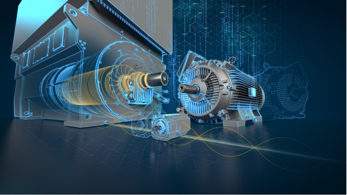
A motor is a device that changes a form of energy into mechanical energy to produce motion. Electric motors convert electrical energy into mechanical energy.
In Electronics and Robotics applications, motors are used as actuators.
An actuator is a device that produces a motion by converting energy and signals going into the system. The motion it produces can be either rotary or linear.
The component that motors actuate can be anything such as it wheels, legs, tracks, arms, fingers, sensor turrets, camera, or weapon systems etc.
Based on the project requirements, we have many types of motors at our Disposal. Below are the most used ones:
- Brushed DC motor
- Brushless DC motor
- Geared DC motor
- Servo motor
- Stepper motor
- DC linear actuator
Brushed DC Motor
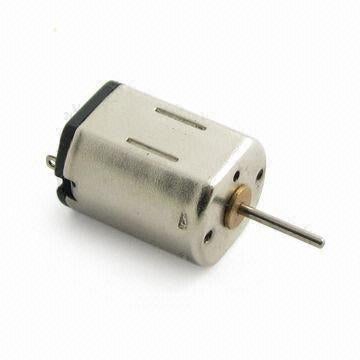
A brushed DC motor is one which uses two brushes to conduct current from source to armature. There are several variations on the brush DC motor, but permanent magnet DC motor (PMDC) is used extensively in robotics. Brushed DC motors are widely used in applications ranging from toys to push-button adjustable car seats. Brushed DC (BDC) motors are inexpensive, easy to drive, and are readily available in all sizes and shapes.
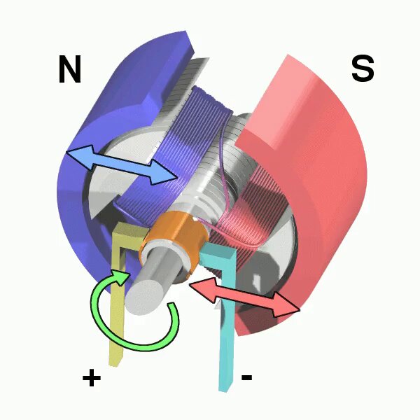
The brush DC Motor consists of six different components: the axle, armature/rotor, commutator, stator, magnets, and brushes. A Brush DC Motor consists of two magnets facing the same direction, that surrounding two coils of wire that reside in the middle of the Brush DC Motor, around a rotor. The coils are positioned to face the magnets, causing electricity to flow to them. This generates a magnetic field, which ultimately pushes the coils away from the magnets they are facing, and causes the rotor to turn.
The Brush DC Motor has two terminals; when voltage is applied across the two terminals, a proportional speed is outputted to the shaft of the Brush DC Motor. A Brush DC Motor consists of two pieces: the stator which includes the housing, permanent magnets, and brushes, and the rotor, which consists of the output shaft, windings and commutator. The Brush DC Motor stator is stationary, while the rotor rotates with respect to the Brush DC Motor stator.The stator generates a stationary magnetic field that surrounds the rotor. The rotor, also called the armature, is made up of one or more windings. When these windings are energized they produce a magnetic field. The magnetic poles of this rotor field will be attracted to the opposite poles generated by the stator, causing the rotor to turn. As the motor turns, the windings are constantly being energized in a different sequence so that the magnetic poles generated by the rotor do not overrun the poles generated in the stator. This switching of the field in the rotor windings is called commutation.
Unlike other electric motor types (i.e., brushless DC, AC induction), BDC motors do not require a controller to switch current in the motor windings. Instead, the commutation of the windings of a BDC motor is done mechanically. A segmented copper sleeve, called a commutator, resides on the axle of a BDC motor. As the motor turns, carbon brushes slide over the commutator, coming in contact with different segments of the commutator. The segments are attached to different rotor windings, therefore, a dynamic magnetic field is generated inside the motor when a voltage is applied across the brushes of the motor. It is important to note that the brushes and commutator are the parts of a BDC motor that are most prone to wear because they are sliding past each other.
Applications:
- Toys
- RC Servos
- Gear Motors
Advantages:
- Inexpensive
- Lightweight
- Reasonably Efficient
- Good low-speed torque
Limitations:
- In addition to the audible whine from the commutator brushes, these motors create a lot of electrical noise which can find its way back into other circuitry and cause problems.
Geared DC Motor
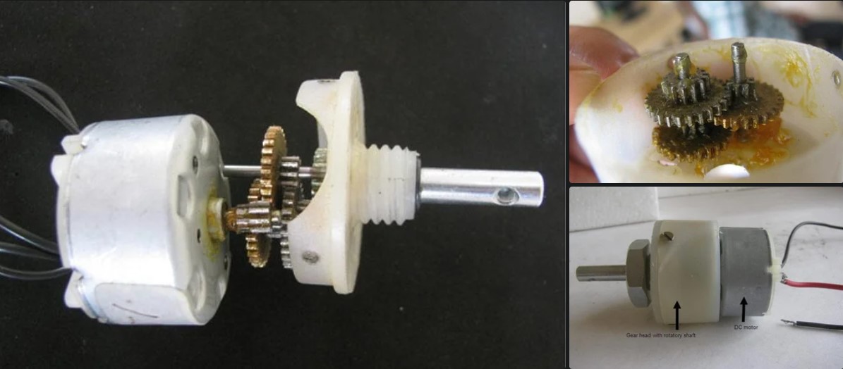
Geared DC motors can be defined as an extension of DC motor which already had its Insight details demystified before. A geared DC Motor has a gear assembly attached to the motor. The speed of motor is counted in terms of rotations of the shaft per minute and is termed as RPM .The gear assembly helps in increasing the torque and reducing the speed. Using the correct combination of gears in a gear motor, its speed can be reduced to any desirable figure. This concept where gears reduce the speed of the vehicle but increase its torque is known as gear reduction. This Insight will explore all the minor and major details that make the gear head and hence the working of geared DC motor.
Working of the DC Geared Motor
- The DC motor works over a fair range of voltage. The higher the input voltage more is the RPM (rotations per minute) of the motor. For example, if the motor works in the range of 6-12V, it will have the least RPM at 6V and maximum at 12 V. In terms of voltage, we can put the equation as: RPM= K1 * V, where, K1= induced voltage constant V=voltage applied.
- The working of the gears is very interesting to know. It can be explained by the principle of conservation of angular momentum. The gear having smaller radius will cover more RPM than the one with larger radius. However, the larger gear will give more torque to the smaller gear than vice versa. The comparison of angular velocity between input gear (the one that transfers energy) to output gear gives the gear ratio. When multiple gears are connected together, conservation of energy is also followed. The direction in which the other gear rotates is always the opposite of the gear adjacent to it. In any DC motor, RPM and torque are inversely proportional. Hence the gear having more torque will provide a lesser RPM and converse. In a geared DC motor, the concept of pulse width modulation is applied.
For example, an unloaded DC motor might spin at 12000 rpm and provide 0.1 kg-cm of torque. A 225:1 geardown is added to proportionally reduce the speed and increase the torque: 12000 rpm / 225 = 53.3 rpm and 0.1 x 225 = 22.5 kg-cm. The motor will now be able to move significantly more weight at a more reasonable speed.
In a geared DC motor, the gear connecting the motor and the gear head is quite small, hence it transfers more speed to the larger teeth part of the gear head and makes it rotate. The larger part of the gear further turns the smaller duplex part. The small duplex part receives the torque but not the speed from its predecessor which it transfers to larger part of other gear and so on. The third gear’s duplex part has more teeth than others and hence it transfers more torque to the gear that is connected to the shaft.
Applications:
- Robot Drive Trains
- Radio Control Vehicles
- Cordless Tools
Advantages:
- Speed Reduction - Many DC motors simply run too fast to be useful in direct-drive applications.
- Increased Torque - A lot of work can be coaxed from a relatively small motor if fitted with a suitable gear train.
Limitations:
- This is especially a problem with low-cost plastic gear trains used with low-voltage motors.
- The extra resistance can make these gear-trains balky at low speeds.